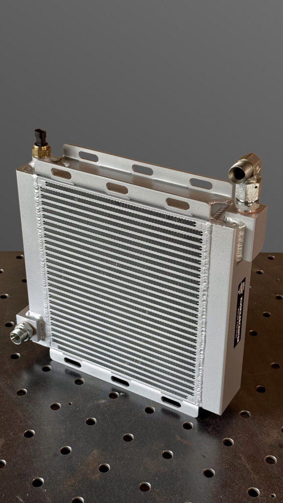
Custom oil cooler for a wood chipper mill
Sometimes a cooler arrives at the workshop where it is clear at first glance that a repair will not be the right answer.
This time it was the hydraulic oil cooler of a wood chipper mill. The original failed after a valve fault in the system. The result was a sudden pressure load that damaged the cooler and made it leak.

With damage like this the question is always the same. Repair the existing one or build a new one?
We went for the second. Not because the old one could not somehow be patched, but because a cooler on a machine like this has to work reliably again afterwards. A work machine does not need a cooler that is just about sealed. It needs a heat exchanger that can take the conditions it was fitted for in the first place.
So we built a completely new custom aluminium oil cooler.
When a cooler is not just a cooler
On a chipper mill the hydraulics are under load all the time. Pumps create flow and pressure, the oil drives hydraulic motors and working elements, and part of that energy inevitably turns into heat.
As oil temperature rises, its viscosity changes. That affects lubrication, seals, pumps, valves and the life of the whole hydraulic system. The job of an oil cooler is simple to describe and a little harder to get right. It has to take enough heat out of the oil without creating an unacceptable pressure drop or restricting flow.
The original was damaged by a fault elsewhere
The cause was not in the cooler. A valve fault created an abnormal pressure load, and the heat exchanger was the part that took the consequences.
That is an important difference. If a cooler leaks from corrosion or age, you are mainly solving the cooler. If it was damaged by excess pressure, the replacement has to be built with an understanding of what happened in the system. So the question is not how to make the same cooler, but what the new one actually has to take and do in this machine. More on the three routes is on our services page.
From a damaged original to a new design
The original served as a starting point. From it we took the external dimensions, the position of the connections, the mounting method and the space available on the machine. But we did not build the new one by simply copying the old part.
First the design had to be thought through again. A 3D model set the position of the core, the connections, the mounting points and the rest of the elements.
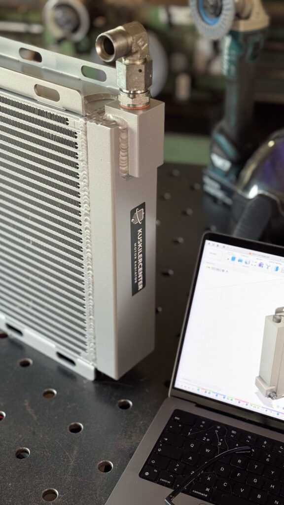
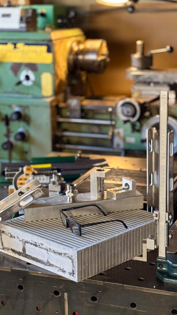
This is the part of the work a customer barely sees in the finished piece. On the bench there is only a piece of aluminium at the end. Behind it are measurements, planning and a good number of decisions that make that piece actually fit the machine.
A bar-and-plate core for a demanding environment
For the new cooler we used an aluminium bar-and-plate core, a robust plate and fin heat exchanger construction. These are used where mechanical strength, compact size and the ability to take higher pressure and thermal loads matter.
The core is built from layers of channels separated by plates and fins. Oil runs on one side, air passes through the fins on the other. Heat makes its way from oil, to the aluminium core, to the fins, to the air.
It sounds simple. With any heat exchanger several things have to line up at once. Enough oil flow, enough surface for heat transfer, suitable air flow, an acceptable pressure drop, and a construction that survives the working conditions of the machine.
The connections did not come off a shelf
When you build a cooler to measure, the world of universal parts ends quickly. The connections had to suit the existing hydraulics and the new construction at the same time. Some elements were made by conventional machining and on the CNC.
It is not only the thread and the outside diameter that matter. It is the internal passages, the material thickness around the fitting, the position relative to the core and enough room for a sound weld. These details are where a series product and a one off piece part ways.

TIG welding aluminium
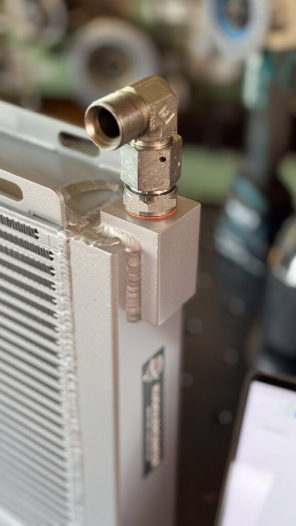
With the core, connections and brackets ready, assembly followed. The aluminium components were joined by TIG welding.
Such a weld has no decorative job. The joint has to be tight, mechanically strong and controlled enough not to damage or needlessly overheat the core. The connections take the most attention, because through them the cooler becomes part of a pressurised hydraulic system.
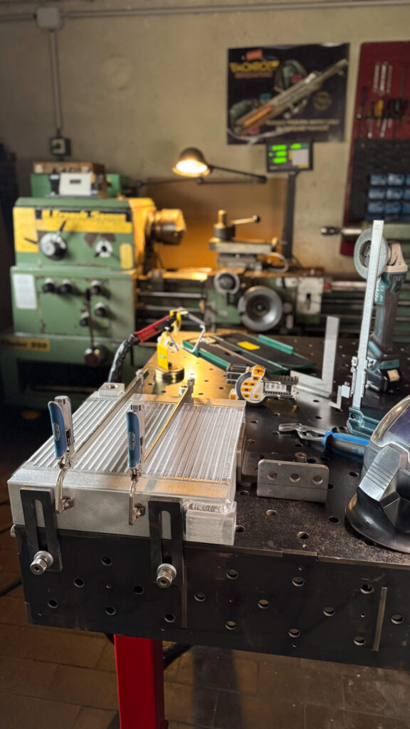
A cooler is also not just a core and two fittings. It has to be mounted on the machine, so we made the mounting parts and brackets and adapted them to the fitting position. Here the 3D design pays off again. Instead of finding out at the end that a fitting sits a few millimetres too close to a bracket, those things are solved before the first piece of material reaches the machine.
The pressure test has the last word
Before a cooler leaves the workshop, the thing you cannot judge by eye has to be checked. Tightness. After welding the new cooler went on the pressure test, and only once it passed was it ready to be fitted.
On a piece whose predecessor was damaged by a pressure event in the system, that step carries even more weight. A good weld looks good. A tight, properly built cooler has to prove it under pressure.
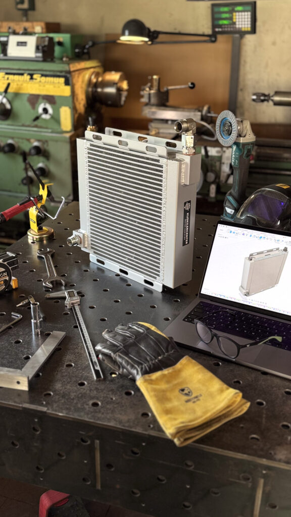
Old and new, side by side
In the last photo both coolers stand together. The original on the right, the new one on the left. That is perhaps the best summary of the project.
The aim was not to make something that merely looks like the original. The aim was a functional replacement oil cooler that fits the machine, has the right connections and mounting points, and is built for a demanding working environment.
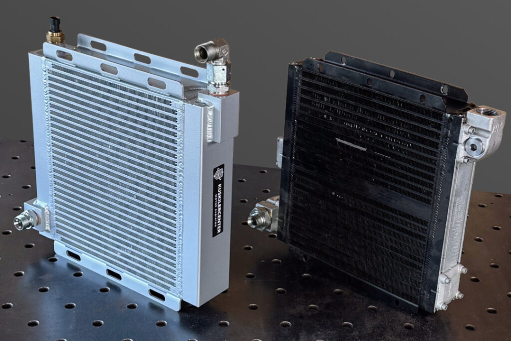
From the first measurement to the final pressure test it was made in one workshop. 3D design, CNC and conventional machining, a bar-and-plate core, machined connections and brackets, TIG welded aluminium, pressure tested.
When everything is done right, the cooler simply sits in its place and does its job. And that is the biggest compliment it can get.
When a series cooler is not the answer
Custom work usually starts where the standard route fails. The original part is no longer available, the existing cooler cannot be repaired, the machine has been modified, different cooling capacity is needed, or, as here, a failure calls for a completely new heat exchanger.
Then the work is not only building a piece. First you have to understand what is being cooled, how much heat has to be removed, what the flows and pressures are, how much space there is and what conditions the machine really works in. Only then come aluminium, fins and welding.
Have a similar case? Send photos, dimensions and machine details and we will tell you what makes sense. We ship across Europe.
Behind every cooler, a craftsman.